| Introduction | Last Updated • November 22, 2011 | |||||||||||||||||||||
In order to understand how tectonic deformation occurs, we need to introduce a system of coordinates that tells us about the orientation of the structures in space. Such a system is based on the strike and the dip of a surface.
Strike and dip, also known as the attitude of a surface, are mainly used during the geological mapping of an area, and will both be described within that context in the following section.
Strike and Dip | Last Updated • November 22, 2011 |
Most of the time, data collection (stratigraphic, paleontological, structural, etc.) occurs in the field. Geologists record information from a series of different outcrops. An outcrop is simply a rock column exposed at the surface, whether naturally (because of erosion or mountain building) or artificially (because for instance of a road cut, a tunnel, or an excavation).

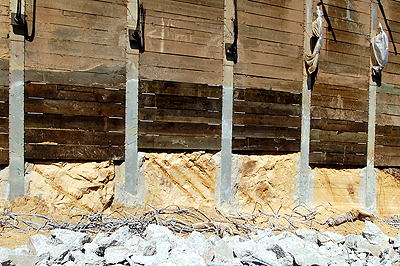
A natural outcrop, caused by river erosion
An outcrop caused by human activity Armed with a topographic map, the geologist records observations about the rocks he sees, and he then plots, among other things, a variety of different symbols recording anything he sees, from the rock type to its structures. One of the most important things a geologist has to note is the attitude of the sediemntary rocks in the area. With these data, the geologist is able to create a geologic map.
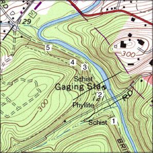 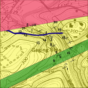
A topographic map (left) and a geologic map (right) of the same area
In the following illustration we can see a very simple geologic map of a flat area (no topography). There are three different kinds of rocks, represented by different colors and symbols: a shale, a sandstone, and a limestone. There are also five T-shaped symbols, with the number 30 by their side. These symbols represent the attitude (strike and dip) of the sedimentary layer at the exact position in the field where it is plotted on the map. The strike and the dip of the layers are represented, respectively, by the long arm of the T and by the short arm of the T. The number by the symbol indicates the angle of tilt of the dip with respect to the horizontal surface. This whole concept can also be seen in the cross section at the bottom of the illustration: the layers are all tilted by an angle of 30° to the left with respect to the horizontal surface, as shown by the symbols on the map.
 From © Plummer, C.C., and Carlson, D.H., 2008. Physical Geology (12thed.), McGraw-Hill
But what are the strike and the dip of a layer, or of any surface in general? When a layer is tilted, it could be tilted in any direction. It could be thought of as an inclined plane. This inclined plane would intersect a horizontal plane along a line. That intersection is the strike. This line (the strike) would make a unique angle with respect to the (geographic) North. This angle can be measured in the field with a compass, making it possible to plot the strike and its orientation relative to the North on a map. The strike is represented by the long arm of the T in the T-symbol, and its angle to the North is simply visible on a map because we are drawing it on the map at that angle (remember that all maps have North at the top). The dip is simply the angle of maximum inclination of our layer. This is measured perpendicularly from the strike. That would be the direction along which a ball would roll down the slope if it where to be put on the layer surface: the ball would always roll in a direction at 90° from the strike. Hence the dip is represented on a map by the short arm of the T (at 90° from the long arm of the T, the strike, and from its middle). The dip points in the direction of tilt. The number associated with the T on a map is the angle of tilt.  From © Plummer, C.C., and Carlson, D.H., 2008. Physical Geology (12thed.), McGraw-Hill
|
Magnetic Declination | Last Updated • November 22, 2011 |
Geologists in the field can measure strike and dip with a compass. The compass needle points towards the Magnetic North Pole. As you know from our previous classes on Magentic Stratigraphy, the Geographic North Pole and the Magnetic North Pole do not coincide: the difference between the angle measured by a compass andthe real angle to the Geographic North is called Magnetic Declination. As a consequence, it is necessary to correct for declination, which is known for every position on Earth.
[from Geomag.org, 2008] This figure shows the values of Magnetic Declination on Earth for the year 2010 (remember that the magnetic poles move every year, and as a consequence, Earths' magnetic field is subject to continuos variations). Bottom left is a view of the northern hemisphere. Bottom right is a view of the southern hemisphere. In red are the lines of the magnetic field with eastern declination, in blue are the lines of the magnetic field with western declination. In green are, respectively, the North and the South Magnetic Poles.
 Notice that this second image is older: while in this map the 0 (zero) line is right off the coast of eastern Florida, in the 2010 image it has already moved to the right by a significant amount: you can see the 0 line above the Mississippi delta in Louisiana.
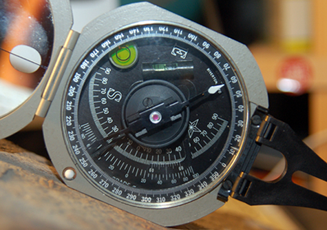
 This image shows a compass with the adjustment for the magnetic declination value for southern California: the pin of the compass (to the right), which should be set at a standard 0°, is now indicating a value of 14°. In this way, when reading the strike of a layer (or any surface) on the compass, we do read the real value (oriented to the Geographic Pole) and not one affected by the declination (oriented to the Magnetic Pole), because we have already corrected for it. Notice the level bubble in the upper left, indicating that the compass was on a horizontal surface. The strike at this location is then 65°, as indicated by the white tip of the magentic needle within the compass. | |
Strike and Dip Symbols | Last Updated • November 23, 2010 |
A strike of 0° would be represented by a vertical long arm of the T. But that would also be true for a strike of 180°. How do we tell one from the other? By convention, if the dip is to the right, the strike is 0°, if it is to the left, the strike is 180°. In the following figure you can see how the strike (and the dip also) change in increments of 45°, starting from 0° and ending with the full circle at 360°. Keep in mind that this is an example to illustrate strike and dip. The number you see is the angle of strike, which you will NEVER see on a map because it is simply given by the rotation of the long arm of the T. 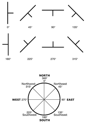 [©Alessandro Grippo, November 23, 2009]
Strike variations from 0° to 360°, shown here in increments of 45°
Can strike and dip be measured at all times? Not always. Think about it: if the layer is horizontal, there is of course no intersection with a horizontal plane (no strike) and there is no dip (the layer is not tilted). What if the layer is vertical, that is at its maximum tilt of 90°? In this case, we can measure both strike and dip. For both these scenarios we use special symbols: two parallel segments (no dip) for vertical layers, and a cross inside a circle for horizontal layers. 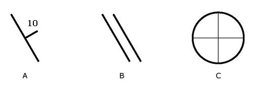 [©Alessandro Grippo, November 23, 2009]
How do we measure strike and dip with a compass? Here are a few images that might help understanding the use of the compass:
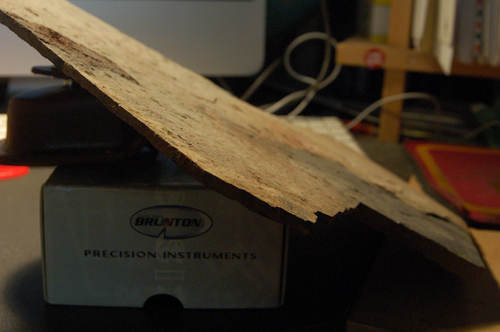
The image above simply shows a dipping surface, an actual slab of Cambrian shales, representing a tilted sequence.
The image above shows the measurement of strike: the compass is in horizontal position (as indicated by the bubble to the left),
The image above shows the measurement of the dip: the compass is directly on the surface of the layer, at 90$deg; from the strike.
| |||||||||||||