 |
|
|
| |
| Event Stratigraphy | Last Updated • May 17, 2016 | |
EVENT STRATIGRAPHY is the correlation of sedimentary sequences via marker beds or event horizons.
These beds and horizons represent synchronous surfaces (surfaces that developed at the same time),
and as a consequence they would separate an older sequence below them from a younger sequence above them.
In particular, a marker bed is a bed, or horizon (a thin subdivision of a layer)
with characteristics distinctly different from those of the host sediment above and below it.
A marker bed can be easily traced over long distances.
An event horizon is a discontinuity surface in an otherwise "normal" sequence,
or a layer with exceptional fossil content, or with specific characteristics within a sequence.
An event can be any kind of depositional, non-depositional or erosional episode
that has occurred synchronously (at the same time) within a sedimentary basin.
These episodes or events are mainly controlled and/or triggered by the physical environment
(for instance, volcanic eruptions, tsunamis, turbidites, storms, etc.).
Still, some events do not affect directly the sedimentary record but rather the faunas and floras.
As a consequence, the event is marked by a change or an anomaly in the fossil record.
- Depositional Events
Depositional events occur within hours or days, or instantaneously from a geologic point of view.
Examples of synchronous deposits are:
- Shallow-marine storm sands (Tempestites), and Tsunami deposits
- Gravity Flow deposits and Turbidites
- Deposits controlled by relative sea-level change
- Continental deposits, such as those left by sheetfloods and flash floods
- Volcanic ash layers and other volcaniclastic (pyroclastic) sediments, known as tephra
- Non-Depositional and Erosional Events
Non-depositional and erosional events do not create distinct beds (there is no sediment available!)
but rather leave a trace, a mark, at a specific surface or horizon.
Many of these events are limited in areal extension and may not be important in correlation. Only the few events that occur over wide areas can acquire a more global role. Examples are:
- On land: paleosols, coal seams, karst surfaces
- Under water: lag deposits (deposits of material "left behind" by currents or waves in shallow waters, such as shell beds, coarse sands beds, beds of minerals and concretions that form and/or concentrate in these conditions)
- Other Rare Physical Events
Events of this kind would still be synchronous, but would only occur occasionally:
- Shallow-marine storm sands
- meteorite impacts (such an impact would form characteristic sedimentary layers and/or leave behind traces of a specific elements, as in the case of the iridium at the K/Pg boundary)
- earthquakes (earthquakes might trigger the formation of distinct deposits, called seismites, that would be synchronous over a certain area)
- Biological Events
The sudden appearance of new taxa in the rock record usually reflects a drastic change in environmental conditions (a climate change, a change in water currents or chemistry, a change in the amount of nutrients, a change in the oxygen content of the water, etc.).
| |
| Seismic Stratigraphy | Last Updated • May 17, 2016 | |
SEISMIC STRATIGRAPHY involves the interpretation of stratigraphy and depositional facies
from seismic reflections data generated when artificially produced
seismic (or acoustic) waves bounce off physical discontinuities within buried sediments.
In other words, man-made vibrations produced at Earth's surface or in ocean water generate seismic waves.
Seismic waves can be refracted (transmitted through) and reflected (bounced back) by discontinuities encountered in their path
such as rocks, marker beds, or horizons (for instance, unconformities) buried underground.
The waves that bounce back to the surface are used to generate a seismic profile.
The seismic profile, which represent discontinuities in time and not in space, is then interpreted.
An example of an interpreted seismic profile

Seismic profiles represent cross-sections of Earth's interior, measured in time.
Time can be later converted to depth (space) using the approximate speed of seismic waves through the different kinds of rocks encountered,
through the correlation with geophysical tools profiles, and through direct matching with rocks as encountered during drilling.
The black lines you see in a seismic profile are called reflectors.
Each reflector represents something "different" that the seismic waves encounter.
As said above, it could be a rock layer with distinctive properties, or an unconformity,
or in general a discontinuity, something that interrupts the regular pattern of deposition.
The depth of a reflector (and hence its position) on the profile is estimated by
multiplying the speed of the seismic wave (which is known for each different lithology)
by the time that it takes for the wave to reach an individual reflector and come back to the surface.
Since the wave travels to the reflector and back, it will give us a double distance. Then we have to divide by 2.
Depth = Speed * Time / 2
Once the profile is readied for interpretation, geologists locate horizons and layers on it,
but also unconformities, structures, folds, and faults.
It is also possible to find evidence for the presence of oil and natural gas,
or at least for the conditions that would be necessary for their presence.
Geologists would then project (vertically) on the section any well that has been drilled in the area.
Wells would allow exact matching of the kind of rock found for every depth encountered by the well.
Then rocks can be matched to specific horizons (reflectors) on a seismic line.
The profile reproduced above shows distinct patterns that allowed geologists to trace the green line,
separating a sequence of relatively undisturbed and more recent sedimentary rocks layers above it
from a sequence of non-continuous older layers (yellow and blue) below,
in which faulting, probably caused by tectonic activity, has occurred.
Since the faults only cut the yellow and the blue refelctors, we can safely say that
this kind of tectonic activity ceased in this area before deposition of the green reflector.
Not only: since the displacement of the blue and the yellow reflectors caused by motion along the fault is different,
we can say that movement along the fault was continuous and happening during the sedimentation,
or otherwise the displacement of the two horizons would have been the same.
Notice to the far right the oil rig symbol and a vertical line right below it, to indicate an actual oil well drilled at that location.
(This is a real published section. Names and locations have been removed)
The well was positioned there in order to reach the top of a buried structure
(a small fold called an anticline) close to the upper end of a normal fault.
In the right conditions, anticlines would prevent oil and natural gas from moving upward and disperse
(what would be called a structural trap, or a place that traps petroleum because of a tectonic structure),
and a fault might further seal a possible petroleum pathway and keep hydrocarbons trapped.
Seismic stratigraphic studies and profiling allow geologists to identify these petroleum-bearing layers and tectonic structures underground.
Reflections of seismic waves occur in general where there is a vertical change in rock type.
These vertical changes are fundamental to stratigraphy.
They can be caused (if you do not consider faulting) by bedding or layering surfaces (the boundary between different layers),
unconformities, and facies boundaries (both of which might not be synchronous)
It is then possible to divide a seismic profile into a package of similar reflections,
and thus identify distinct sequences, which are interpreted and correlated.
Sequences are then studied individually as separate episodes of sediemntation or erosion
and are at the heart of what we call sequence stratigraphy.
One thing we have to keep in mind is that this kind of data is very precious for a geologist:
these data represent a window into the underground structure of an area, which would otherwise be unreachable.
These data are also very expensive to gather,
and it is usually only oil companies who can invest huge amount of money in seismic operations.
Billions of dollars are spent daily for geologic exploration with the purpose of finding economically suitable oil fields.
Seismic profiles (and other proprietary data) belong to individual oil company,
and they are only occasionally made public (to governments, scientists and universities)
after a certain amount of years, if and when the economic interest for an area disappears.
| |
| Geophysical Log stratigraphy and Coring Operations | Last Updated • May 17, 2016 | |
Once a seismic profile yields promising information about oil and gas, oil companies can decide to drill a well.
The rocks encountered during the drilling operations are brought to the surface
and put in their relative sequence according to the depth at which they were found.
A lithostratigraphic profile is then reconstructed based on cuttings,
the fragments of rock destroyed by a diamond bit during perforation.
The way this works is through a system of hollow drilling pipes.
Drilling implies fracturing rocks at great depth, under high pressure and at high temperature
and then bringing the broken fragments of rock, the cuttings, to the surface
both for study and to clear the way to the drill bit.
So we need a hard enough drill bit, a system to keep it cool, and a system to bring everything up.
The drill bits are made of industrial diamonds, the hardest known mineral
which crushes all rocks encountered at depth.
A mixture of water and mud, often stabiulized with additives such as barite
is circulated through hollow pipes from the surface to the drill bit.
It then leaves the bit through holes, picks up the cuttings, and comes back to the surface
using the space between the pipes and the borehole itself.
At the surface, the circulation mud is cleared of cuttings and sent back into the well.
Sometimes these samples are not enough, and it is important to obtain proxy information about the rocks at depth:
during drilling operations it is a common procedure to run geophysical wireline logs in the well
to collect borehole data and construct a geophysical log stratigraphy.
What kind of information is collected? Here is a tentative list (new tools are continuously developed)
Rock Samples:
- rock fragments from the bottom of the well
- small rock cores from the side of the well
- longer rock cores from the bottom of the well
Geophysical Proxy Data:
- subsurface pressure condition
- subsurface analysis of fluids in rocks (water, salt water, oil, gas, etc.)
- subsurface temperature measurements
- size of the drilling borehole
- electrical resistivity of the rocks encountered
- spontaneous potential of the rocks encountered
- subsurface radioactivity levels
- subsurface rock porosity
- subsurface rock density
- speed of acoustic waves in the rocks encountered
- tilting (inclination) of the layers
How are the data collected?
The data are acquired through electric/nuclear tools that are at times operating during drilling operations.
Most of the time though, the more sophisticated tools are run in the well after this has been stabilized.
After extracting the drilling pipes from the well, the geophysical tools are sent to the bottom.
The tools are then pulled up back to the surface at a constant and known rate,
measuring the geophysical parameters of the surrounding rocks in the meanwhile.
Measurements are recorded and plotted on a graph as a function of depth.
This example is an electrical resistivity log from Gray County, Kansas (from the Kansas Geological Survey / University of Kansas)
How are the data interpreted?
Once data are available, they are interpreted for type of rock and fluid content.
This allows either to match rocks with existing lithostratigraphic units or to create seismostratigraphic units.
These units are then used for stratigraphical correlation and analysis like other units are.

This image shows vertical logs of different rock properties measured in a well.
We can see how not only we get different responses from different rocks as a whole
(for instance, compare shales to sandstones and limestones),
but also from unfractured vs. unfractured rocks (look at the different profiles within the porous limestone)
from the presence or absence of substances in the pores or fractures of what then becomes a reservoir
(look at what happens in presence or absence of gas)
and in some cases even from their different characteristics
(for instance, do we have liquids or gases? If we have liquids, is it oil or water? If it is water, is it hot or cold, salty, brackish or fresh?)
In special cases, it might be necessary to obtain a core from our subsurface section.
A core is, in a few words, a cylinder of rcok obtained from a drilling well through an empty drilling pipe
with sawing diamonds not on a bit but on a drilling crown.
This means that we are sending down a hollow pipe that fills up with a cylinder of rock with depth.
Once we reach the desired depth, the bottom of the pipe is closed and the core is then extracted.
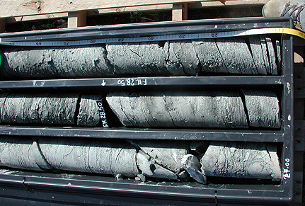
Core showing finely laminated euxinic pelites with layers of gypsum.
Notice the shoe and the centimeter scale for reference.
Miocene from around Rimini, Italy. Photo © Alessandro Grippo
Go to part 1 | Go to part 2 | Go to part 3 | Go to part 4 | Go to part 5 | Go to part 7 | Go to the Images Page | Go to the Home Page
© Alessandro Grippo, 2008-2016 | | |
|